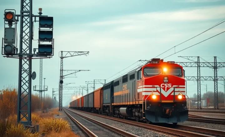
What Makes Railway Engineering So Complex—Tracks, Signals, and Safety

David Shaw
July 7, 2026
A train running on schedule seems like one of the simpler things modern infrastructure achieves. Steel wheels on steel rails, following a fixed path, stopping at known locations. Compared to air travel, with its three-dimensional routing, dynamic weather, and complex airspace management, railways might seem straightforward. They are not. The engineering behind a modern railway network—covering track construction and maintenance, signaling and safety systems, train control, and the management of complex mixed-traffic networks—involves problems that have been worked on for nearly two centuries and remain genuinely difficult.
What makes railways hard isn’t any single element. It’s the intersection of physical constraints, safety requirements, operational complexity, and legacy infrastructure that forces engineers to solve problems that have no clean solutions.
The Track: More Than Rails on the Ground
A railway track is an engineered structure designed to carry enormous loads at speed while maintaining precise geometry over millions of load cycles. A heavy freight locomotive can weigh 150 tonnes, and a fully loaded freight train might exert forces in the millions of newtons at any given wheel-rail contact point. High-speed passenger trains impose different challenges—lower weight but higher speed and aerodynamic forces.
The track structure consists of rails (the two parallel steel bars), fasteners (clips and plates that attach the rail to the sleeper), sleepers or crossties (the lateral elements that support the rail and transmit load to the ballast), and ballast (crushed stone that distributes load and provides drainage and stability). Each of these components is engineered to specific tolerances that govern how loads are distributed and how long the structure lasts before maintenance is required.
Modern rails are continuous-welded—long sections joined by thermite welding or flash-butt welding into strings hundreds of meters or kilometers long. Eliminating rail joints reduces the “clickety-clack” noise, reduces wheel impacts at joints (which cause accelerated wear), and allows faster speeds. But continuous-welded rail expands and contracts with temperature. A steel rail that’s 100 meters long will expand by about 12 cm between a cold winter night and a hot summer afternoon. If this expansion is unconstrained, the rail buckles—a phenomenon called “sun kinking” that can cause derailments. Rail is pre-stressed during installation to a “neutral temperature” somewhere in the middle of the expected temperature range, and fasteners provide clamping force to resist thermal movement. Managing rail temperature and stress is an ongoing maintenance challenge, particularly as climate change produces more extreme heat events.
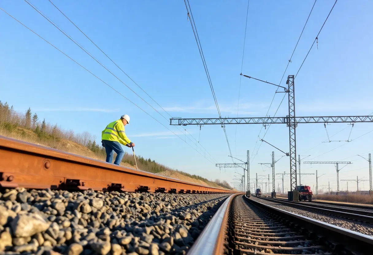
Track geometry—the precise alignment of the two rails relative to each other and relative to the intended path—degrades over time under traffic loading. The ballast compresses and shifts, the sleepers settle, and the rail moves laterally. Track geometry measurement trains run regularly with onboard sensors to detect geometry deterioration before it reaches safety limits. Maintenance crews then perform tamping (lifting the track and vibrating ballast under the sleepers to restore correct geometry), surfacing, and lining (lateral repositioning). This maintenance is continuous—a busy mainline track requires regular intervention just to remain in acceptable condition.
The Switch: Where Geometry Gets Complicated
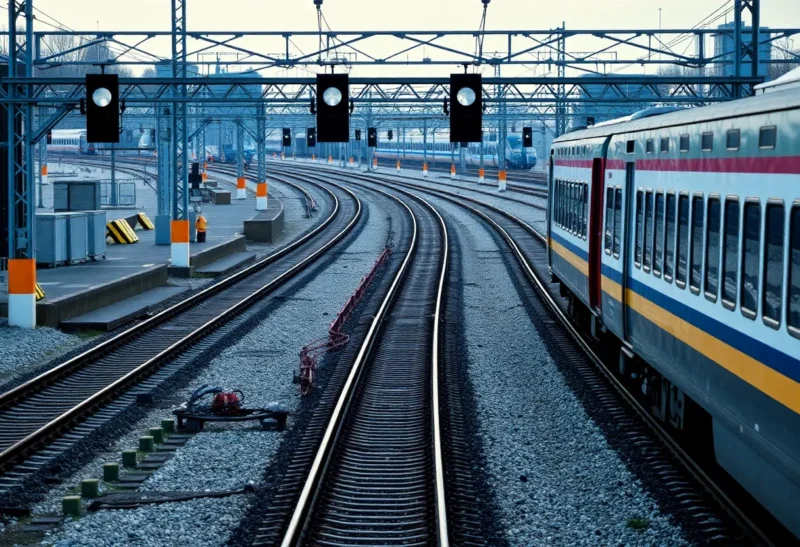
A railway switch (or turnout) allows trains to move from one track to another. The mechanical engineering of a switch involves movable point rails—sections of rail that swing between positions to guide wheels onto either the straight or diverging route. The switch machine moves these point rails, lock mechanisms confirm the points are fully in position, and detection equipment verifies the position before a signal can authorize a train movement.
The geometry at a switch is inherently a compromise. A train wheel has a conical profile and a flange; on straight track, this creates self-centering behavior that keeps the wheel on the rail without active steering. At a switch, the wheel must be guided by the track geometry through a complex section where the geometry transitions. The crossing nose—the point where the two routes physically cross—is a particular challenge: it must be shaped to guide the wheel cleanly regardless of which route is being used, at any expected speed.
High-speed railways require much gentler turnout curves than conventional rail, because lateral acceleration at speed through a tight curve is uncomfortable for passengers and stressful for the track. A high-speed turnout designed for 200 km/h on the diverging route can be several hundred meters long—a significant length of complex, maintenance-intensive track. Managing high-speed network traffic through junctions without losing capacity is a major timetabling and engineering challenge.
Signaling: The Hardest Safety Problem
The fundamental safety problem of railways is keeping trains from colliding with each other. Trains cannot swerve to avoid obstacles—they’re committed to their tracks. Stopping distances for heavy, fast trains can exceed a kilometer. The signaling system must ensure that no two trains are ever in the same section of track at the same time, with enough margin that a train can always stop before reaching an occupied section.
Traditional fixed-block signaling divides the track into sections. Each section is “occupied” when a train is present (detected electrically through the rails) and “clear” when empty. Signals at the entry to each section show green (clear) or red (occupied) to the approaching train. The length of each block is set to be at least the stopping distance of the fastest train on that line at the maximum permitted speed. This is simple and robust, but wastes capacity: the headway between trains must be at least two block lengths (one for the train ahead plus the stopping distance block), and short-distance busy urban routes can move trains only a few minutes apart even with close signal spacing.
Moving-block signaling, used on modern metro systems and some mainlines, continuously tracks each train’s position and calculates a dynamic safe following distance based on each train’s actual speed and braking capability. Instead of fixed sections, each train gets a “movement authority”—permission to move up to a point calculated to ensure safety given the positions of trains ahead. Moving block can increase line capacity by 20–40% compared to fixed block by allowing trains to run closer together when they’re both going slowly and farther apart when running fast.
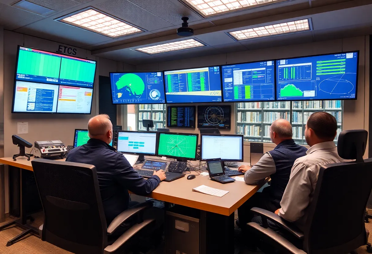
The European Train Control System (ETCS) is the standardized signaling system being deployed across Europe to replace the patchwork of incompatible national systems that make cross-border operation complex. ETCS level 2 uses GSM-R radio communication between the track and the train, with the train’s onboard computer receiving movement authorities and enforcing speed limits automatically. ETCS level 3 is the full moving-block implementation.
The safety integrity requirements for signaling systems are among the most stringent in any engineered domain. Signaling systems are rated to SIL 4 (Safety Integrity Level 4) under the IEC 61508 standard—the highest level, corresponding to a probability of dangerous failure per hour of 10⁻⁸ to 10⁻⁹. Achieving this requires redundant hardware, diverse software implementations, formal verification, extensive testing, and decades of operational validation.
Fail-Safe Design: The Core Principle
Railway safety engineering is built on the fail-safe principle: the system must default to a safe state when anything goes wrong. The canonical implementation is the “closed circuit” for signals: the signal shows green only when the circuit is actively energized and confirmed safe; any failure, break in the circuit, or unknown state causes the signal to default to red. A train stopped by a red signal is delayed; a train authorized through a failed safe check can cause a crash. The engineering chooses delay over collision as the default failure mode.
This principle pervades railway design. Brakes on railway vehicles are spring-applied and air-released: air pressure holds them open; loss of air pressure causes the brakes to apply. A brake failure therefore stops the train rather than leaving it unbraked. Train detection circuits are designed so that a failed component shows a track as “occupied,” stopping trains, rather than showing it falsely “clear.” Interlocking systems—which manage the logic of what switch and signal combinations are permissible—are designed so that any illegal combination (which could route two trains into conflict) is physically prevented.
The Mixed-Traffic Challenge
Many railway networks carry both freight and passenger trains on the same infrastructure. Freight trains are slow, heavy, and can be very long (a mile-long freight train is common in North America). Passenger trains are faster, lighter, and time-sensitive. High-speed trains on the same tracks as slow freight creates a timetabling and capacity problem: the fast train catches up to the slow train quickly, and infrastructure that provides overtaking loops (passing loops where a slower train waits while a faster train passes) must be spaced for the speed differentials involved.
In Europe, this conflict has driven the development of dedicated high-speed rail lines separate from the conventional network, with freight using the conventional network and passenger services split between high-speed and regional operations. In the US, Amtrak operates on freight-owned infrastructure where it has less priority, which contributes significantly to its poor on-time performance. The fundamental tension between different train types sharing infrastructure is not solvable purely through technology—it requires either more infrastructure or acceptance of constraints on one type of service.
Electrification and Power Systems
Electric railways power trains through overhead wires (catenary) or third rails, which carry high-voltage AC or DC power that the train collects via a pantograph or shoe. The power system engineering is substantial: the catenary must maintain contact with the pantograph at speeds up to 350 km/h (for high-speed rail) despite wind, temperature-induced sag and expansion, and the mechanical forces from the pantograph. The wire is pre-tensioned and the system is geometrically designed so the pantograph contact point moves across the wire’s width rather than always wearing the same spot.
Supplying enough power for a busy electrified line requires substations at intervals, traction power cabling, and power system design that manages load fluctuations as multiple trains accelerate and brake across the network. Regenerative braking—where braking trains act as generators and return power to the overhead wire for other trains to use—can recover 15–30% of traction energy on heavily trafficked lines, improving overall efficiency.
Why Old Railway Infrastructure Is So Hard to Upgrade
Much of the world’s railway infrastructure was built in the 19th and early 20th centuries—track alignments determined by steam-era gradient limits, tunnels and bridges built to steam-era clearance gauges, station layouts designed for horse-drawn traffic to and from the terminal. Upgrading this infrastructure to modern standards is extraordinarily expensive: re-aligning a route to allow higher speeds may require new tunnels, viaducts, and land acquisition; upgrading clearance gauges for double-stack freight requires modifying every tunnel and bridge on the route; electrification requires new civil engineering for catenary supports on top of the electrical work.
This legacy creates a constraint that aviation and road transport don’t face in the same way: the investment required to improve railway performance significantly is measured in billions per mile for major upgrades, making radical improvement politically and financially difficult even when the long-term economics favor it. Railway engineering is thus always a negotiation between what’s physically and technically possible and what the existing infrastructure allows within realistic budgets—a constraint that shapes every network planning and upgrade decision.