The Engineering of Modern Elevators: Surprisingly Complex, Rarely Thought About

David Shaw
July 7, 2026
You step into an elevator, press a button, arrive at your floor. The whole experience is designed to feel trivially simple—a box that goes up and down. What’s actually happening inside the shaft, machine room, and control system to make that happen safely is a multi-disciplinary engineering problem that has produced some elegant solutions to genuinely hard physics and safety challenges. Elevators are among the most safety-critical systems in everyday civilian use, and their design reflects that status in ways that aren’t visible from inside the cab.
The Basic Traction System
The dominant elevator type in multi-story buildings is the traction elevator. The cab is suspended by multiple steel ropes (called hoist ropes or wire ropes) that run over a sheave—a grooved wheel—at the top of the shaft. On the other side of the sheave, counterweights hang at the opposite end of the ropes. The counterweights are sized to approximately equal the weight of the empty cab plus 40–50% of the rated load capacity.
This counterweight arrangement is the first elegant engineering solution in elevator design. Without counterweights, the motor would need to lift the entire weight of the loaded cab from zero every time it started from the bottom. With counterweights, the motor only needs to overcome the imbalance between the cab (including its load) and the counterweight plus friction—a fraction of the total weight. This dramatically reduces the required motor power, reduces energy consumption, and allows smoother acceleration and deceleration.
The ropes don’t grip the sheave by wrapping around it—they sit in grooves machined into the sheave surface, and friction between rope and groove provides the driving force. The traction (hence the name) must be sufficient to move the load but must also allow the ropes to slip if the cab overspeed or jams, preventing rope breakage. Getting this traction balance right—enough friction to drive the load, not so much that the safety system can’t arrest runaway motion—is a specific design calculation that codes mandate.
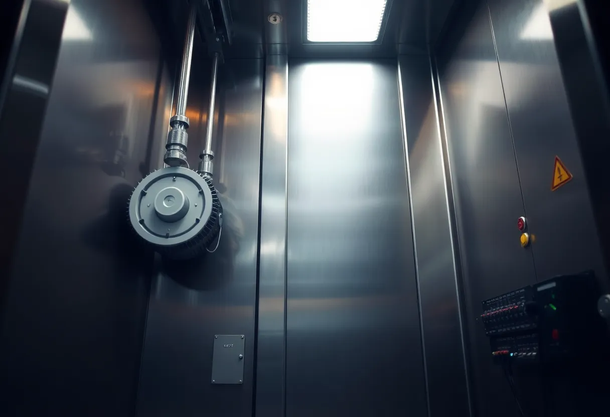
Modern traction elevators typically use gearless machines—direct-drive motors with permanent magnet or variable-frequency drive systems that control speed precisely without a gearbox. Gearless machines are quieter, more efficient, and have less mechanical complexity to maintain than older geared machines. They’re controlled by variable-voltage, variable-frequency (VVVF) drives that smooth out the acceleration and deceleration curve, producing the “soft” feel of a well-tuned elevator.
The Safety System: How Elevators Actually Stay Safe
An elevator cab is a box hanging over a multi-story drop. The safety engineering around this fact is layered, redundant, and rigorously maintained—which is why, statistically, elevator travel is extraordinarily safe and fatal accidents are almost invariably the result of maintenance failure or misuse rather than inherent design failure.
Hoist ropes are massively over-specced. Elevator hoist ropes are rated to carry many times the actual load. Building codes in most jurisdictions require a minimum safety factor of 8:1 for hoist ropes—meaning the ropes can hold at least eight times the maximum load they’ll ever actually carry. Multiple separate ropes are used (typically 4–8), and the system is designed to hold full load even if all but one rope fails. In practice, all ropes failing simultaneously before any inspection would detect them is essentially impossible under a proper maintenance regime.
The governor and safety gear system. Every traction elevator has a separate overspeed governor—a centrifugal device that activates mechanically when the cab exceeds a set speed (typically 115–125% of rated speed). When the governor activates, it trips a linkage connected to safety gears clamped to the guide rails—wedge-shaped grippers that progressively grip the guide rails and bring the cab to a controlled stop. This system is entirely mechanical and operates independently of the electrical control system. It will arrest a runaway cab even with complete electrical failure.
Buffers at the bottom of the shaft. Energy storage buffers (spring or oil hydraulic) at the base of the shaft absorb the cab’s kinetic energy if it reaches the bottom with too much velocity. These are sized for specific cab mass and speed combinations and are tested periodically under load.
Electromagnetic brakes on the drive motor. The traction machine’s motor brake is fail-safe: it’s held open (released) by electrical power and closes automatically when power is removed. In any power interruption, the brake engages immediately, holding the cab in place. This “fail-closed” design means power failure results in stopping, not runaway motion.
Door interlocks. The elevator will not move if any landing door or car door is open. Each door has a mechanical interlock that interrupts the safety circuit when open—the electrical circuit that allows motion. These interlocks are one of the most frequently maintained items in an elevator, because door-related incidents (people falling into shafts when doors open on an empty shaft) are among the most serious elevator hazards.
The Dispatch Problem: How Elevators “Think”
A single elevator in a building is straightforward to control. A bank of multiple elevators serving a tall building is an interesting optimisation problem, and modern elevator group controllers have become significantly more sophisticated over the past 30 years.
Early elevator control used simple rules: send the nearest elevator going in the requested direction. This produces reasonable average wait times but is susceptible to “bunching”—multiple elevators clustering together while other floors wait. Anyone who has watched a bank of elevators where three arrive simultaneously while another floor waits five minutes has observed elevator bunching.
Modern group controllers use destination dispatch—a system where passengers enter their destination floor at a hall panel (rather than just pressing “up” or “down”), and the controller assigns a specific elevator before the passenger reaches the bank. The controller can then optimise across all pending calls: grouping passengers going to nearby floors in the same elevator, distributing load across cars, minimising total wait time across all passengers rather than simply serving each call in isolation.
Destination dispatch systems in large installations use algorithms that consider current car positions, current loads (estimated from load weighing devices in the cab floor), stopping patterns, and queue distributions to minimise a multi-objective function. Some systems use machine learning to model traffic patterns by time of day and day of week, pre-positioning cars near likely pickup zones before peak demand periods (the morning rush to upper floors, the lunchtime exodus, the afternoon return).
The efficiency difference between a well-optimised destination dispatch system and a conventional up/down hall call system in a 40-story building during peak traffic is significant—measurable in minutes of average wait time per day, multiplied across thousands of passengers.
Machine-Room-Less Elevators and the Space Savings
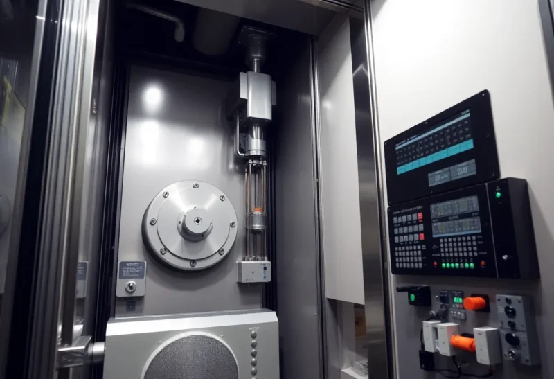
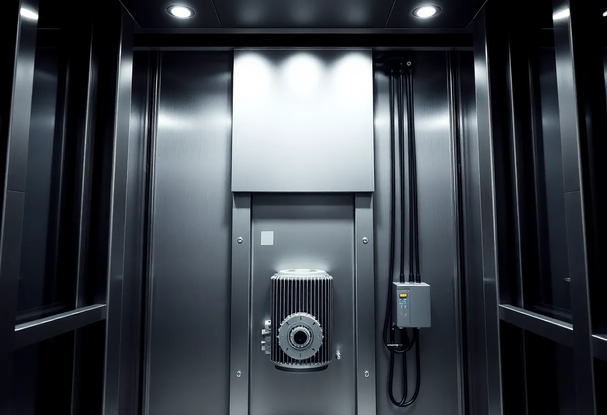
Traditional traction elevators require a machine room above the shaft—a dedicated space housing the traction machine, controller, and associated equipment. This room adds cost (additional space on valuable upper floors or rooftop) and constrains building design. Machine-room-less (MRL) elevators move the traction machine and controller into the shaft itself, eliminating the dedicated machine room.
MRL elevators use compact gearless machines that fit within the shaft headroom, with controllers mounted in a cabinet accessible from a nearby corridor or shaft wall. They’ve become the dominant type for low-to-mid-rise applications (typically up to about 30 floors) in new construction, as the cost savings from eliminating the machine room outweigh the slightly higher cost of the compact machine design.
For very tall buildings (above 30–40 floors), traditional machine rooms or mid-rise machine decks remain common, because the rope length and cab speed requirements become difficult to achieve with compact shaft-mounted machines.
Linear Motor Elevators and Multi-Directional Cabins
The rope-and-counterweight traction elevator has been the dominant design for over a century, but alternative approaches have become commercially available that solve specific limitations:
ThyssenKrupp’s MULTI system (now Hochtief/Thyssen Lifts) uses linear induction motors in the shaft walls to drive cabins that have no ropes. Without ropes, multiple cabins can share a single shaft and move independently, and cabins can move both vertically and horizontally. This enables elevator systems that circulate cabins in a loop—one shaft for up travel, another for down, connected at top and bottom—dramatically increasing the passenger throughput per shaft cross-section. Linear motor elevators are suitable for buildings where traditional rope-based systems would require impractically large machine rooms or shaft allocations.
Hydraulic elevators remain common for low-rise applications (typically 2–4 floors). A hydraulic ram pushes the cab from below, powered by a pump and fluid reservoir. They’re simpler mechanically than traction systems, require no overhead machine room, and are less expensive for short travel distances. Their energy inefficiency (the fluid pumped to raise the cab must be released to lower it, wasting the energy) makes them less suitable for high-traffic or tall applications.
What Regular Maintenance Actually Involves
Modern elevators require monthly to quarterly maintenance under most building codes—not because they’re unreliable, but because the failure consequences are serious enough that finding and fixing problems before they affect safety matters. A typical maintenance visit involves:
- Checking hoist rope wear and tension (ropes are replaced on a schedule well before they reach any safety limit)
- Testing door interlock function (every door, every floor)
- Lubricating guide rails and checking cab guide shoe wear
- Testing the overspeed governor and safety gear trip (a full-speed runaway test is done less frequently but required periodically)
- Checking brake operation and adjustment
- Testing emergency stop and alarm systems
- Reviewing and clearing controller fault logs
Modern elevators increasingly incorporate remote monitoring—controllers that transmit operational data to the service company’s systems, flagging anomalies before they become failures. An elevator controller that records unusual braking patterns, door cycle times outside normal ranges, or load sensor readings that suggest a mechanical issue can be flagged for inspection before a passenger-visible failure occurs. This predictive maintenance approach is reducing unexpected outages in buildings with modern installed equipment.
The Ride Quality Engineering
The technical performance metrics that define elevator ride quality—horizontal vibration, vertical vibration, acceleration, jerk (the rate of change of acceleration), and noise—are specified to very precise tolerances in premium installations. The difference between a well-tuned elevator and a poorly adjusted one is immediately perceptible as the difference between a smooth, quiet, effortless ascent and a jerky, noisy, slightly alarming experience.
Achieving smooth ride quality involves the motor control algorithm (VVVF drive tuning for smooth speed transitions), cab isolation systems (rubber buffers and damping between the cab structure and the frame), rail alignment precision (misaligned guide rails produce horizontal vibration as the cab’s guide shoes track over joints), and counterweight balancing (the counterweight should be balanced to match the average load, not empty or full).
In premium commercial and residential installations, elevator manufacturers measure and tune ride quality with accelerometers in the cab. The ISO 18738 standard specifies acceptable acceleration and vibration limits for passenger elevators—and the premium end of the market aims significantly below those limits, producing elevators where the only cue that you’re moving in a quiet building is the floor indicator changing.
The everyday elevator is a system that has to work reliably thousands of times a day, for decades, carrying passengers over multi-story drops, in ways that require zero operational thought from its users. That it usually succeeds—that elevator travel is statistically among the safest modes of transport in existence—reflects the layered engineering of a system that has been refined for 170 years while remaining substantially invisible to the people who depend on it every day.